How we developed StereoPi v2 overcoming 6 failures along the way
Introduction
The new Compute Module 4 was recently announced. It just so happens that the Raspberry Pi Foundation has provided us with early access to technical documentation and a restricted developer forum long before its official announcement.
After gaining access to the forum, the first thing we did was read the history. You know, there's a big difference between developing on a serial production module and early access to a device that has not even been fully formed yet. It was amazingly interesting to read through the evolution of the changes that were made to Compute Module 4. And then watch early documents with short descriptions turn into large and beautiful datasheets.
General impressions of the new version in one paragraph
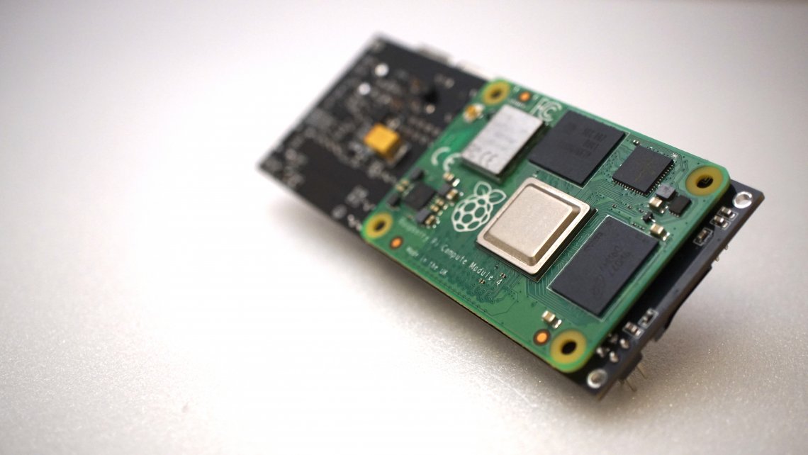
The Compute Module was completely 'rethought'. The previous CM3 was essentially a board with a SoC and key components (such as memory and eMMC) with a huge number of outputs. The CM4 is a full-fledged Raspberry Pi 4 shrunk down to a minimum size with a lot of functionality on board, including its own power supply and small things like HDMI ESD protection. The degree of readiness for work is significantly higher, which allows you to get a finalised device with less effort.
Compared to the regular Raspberry Pi 4, the CM4 has several additional features. In this article, we won't list all the capabilities of the new module – this has already been done for us, for example, in this excellent review by Jeff Geerling. We will walk you through the development process of StereoPi v2 and how the CM4 features influenced it. And we'll honestly describe our failures!
Power
This was the first thing we thought about before designing our board. The power supply for the previous version, Compute Module 3, required special attention. It was necessary to provide (quote from the CM3 datasheet):
That's some list. In the minimum version, we needed at least 3 types of power supply.
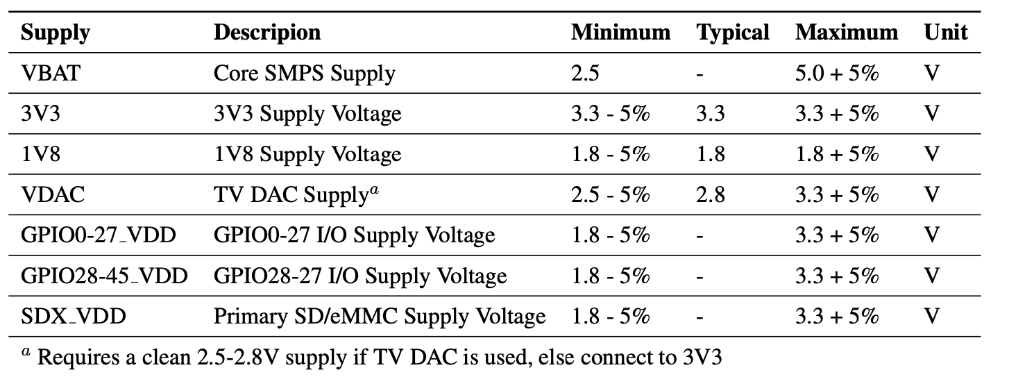
Let's take a look at the power requirements for Compute Module 4:

How do you like it?
This is an actual '5V device'! You just need to provide it with 5 volts, and it does the rest itself.
As a bonus, it also generates power for 3.3V and 1.8V peripherals!
This greatly simplifies the StereoPi v2 circuitry, eliminating our PMIC with its wiring.
A little bit of specifics
The Compute Module 4 is capable of delivering up to 600mA of current to 3.3V and 1.8V buses. The datasheet also indicates that it's advisable not to take more than 300mA from one output. In our case, two cameras, the micro SD and the GPIO pins must be powered from 3.3V. After evaluating the total consumption, we decided to leave the native 3.3V supply from the CM4, without adding a separate 3.3V source.
Be careful, or our first failure
Based on our experience working with the CM3 and a power supply located on our v1 board, all sorts of short circuits caused the StereoPi to fail, but the Compute Module always stayed alive. Perhaps, we and our StereoPi users were just lucky. But with the CM4 you need to be very careful. Abnormal shorts will damage the power supply on the Compute Module itself, and it will become inoperational.
We're used to making contingency plans, and we always try to have several units at hand. It helps to catch bugs by simply comparing the behavior of multiple device instances. So when the Raspberry Pi Foundation announced the availability of engineering versions of CM4, we asked for two Compute Modules (plus a debug board). Unfortunately, one of them died after accidentally short-circuiting the 3.3V and 5V power lines. We safeguard the remaining module by checking the correctness of connections three times. And we remove all metal objects that could theoretically fall on the device and cause a short circuit.
Form factor and failed tricks
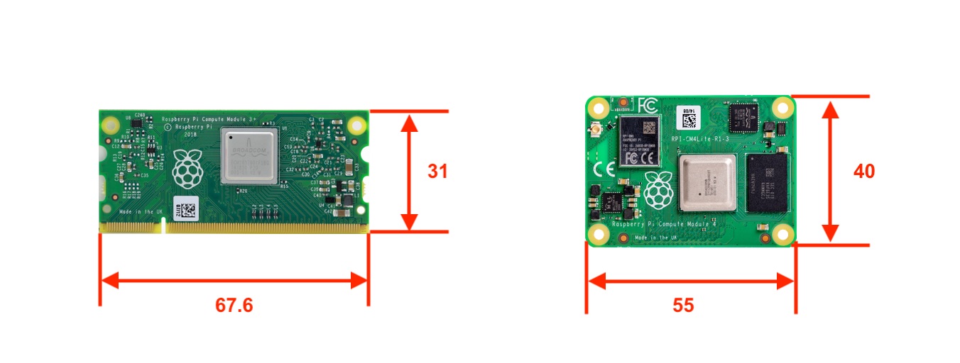
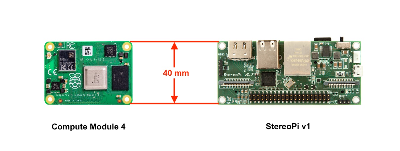
The new version of Compute Module has changed in both size and aspect ratio. The new form factor significantly saves space on the board you're designing.
Let's talk about one funny coincidence first. For almost three years now, our StereoPi board has been 40mm high. Imagine our surprise when the height of the new Compute Module turned out to be exactly the same! We'd be flattered to think that the Raspberry Pi Foundation did this on purpose, but we all know it's just a fortunate coincidence. ☺
Now, about our craving for miniaturization. We have always strived to make our device as small as possible while keeping full-size connectors on board. This is very important for user convenience. We're talking USB-A and Ethernet. Our first version of the StereoPi is still the smallest device on Compute Module 3 with full-size connectors. To achieve this, we used one trick: the large connectors are placed opposite the Compute Module. Their pins stick out from the board right below the CM3, but don't touch the module. There are SO-DIMM connectors of varying heights on the market to accommodate this arrangement.
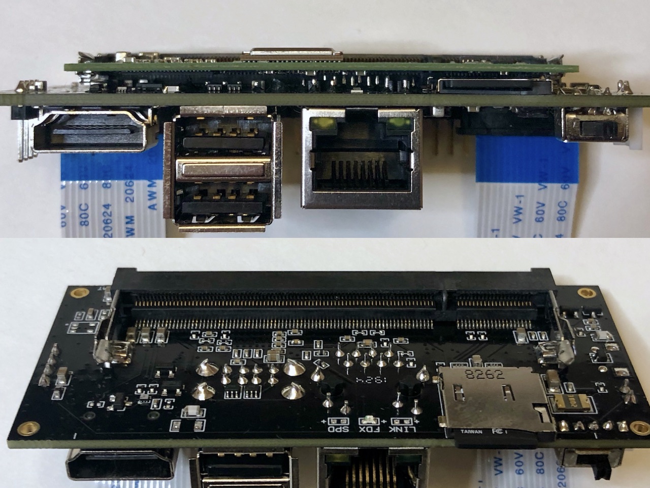
As you must have guessed, this time we did not succeed. The matching connectors for the CM4 (DF40C-100DS-0.4V (51) and DF40HC (3.0) -100DS-0.4V (51), full datasheet) have only two options in terms of height – 1.5 and 3mm with the 100 pins we need. Considering that the CM4 also has a lot of protruding components on its underside, we dismissed this idea as too risky. Yes, there was an option to manually cut off all protruding pins after installation, but this decision seemed 'ugly' to us and could lead to problems in serial production.
So we ended up moving the USB and Ethernet connectors to the side. The trick failed.
CM4 and PiHats width
We considered the option of full mechanical compatibility with 'second floors' for the Raspberry Pi. But then another mechanical limitation came into play. The CM4 is slightly longer horizontally than the spacing of Raspberry Pi's mounting holes.
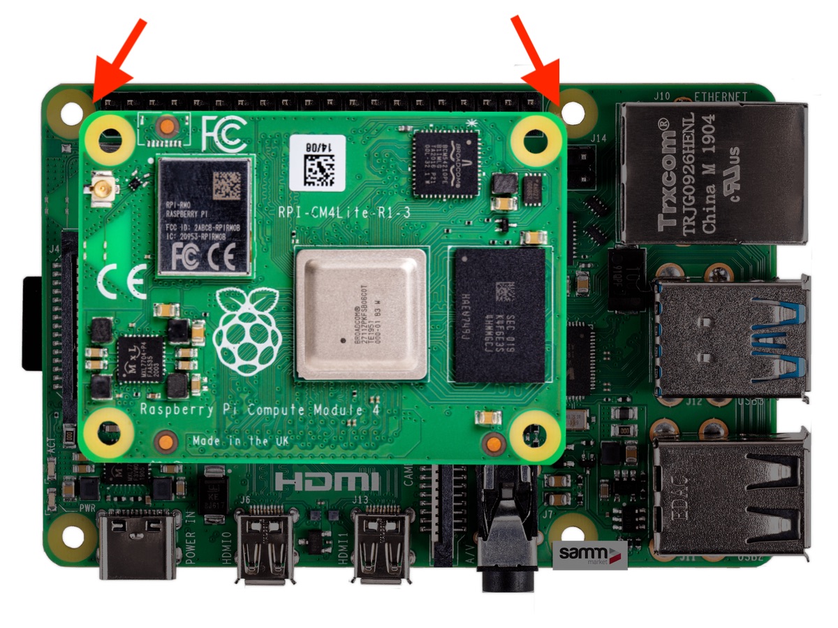
If we rotate the CM4 by 90 degrees, the solution can be achieved. Since we didn't want to change our 'long' form factor, we had to abandon this idea.
No bottlenecks!!! SPEEEEEEEEEEED!!!!!!!!
We praise how wonderfully the issue with high-speed data exchange buses is resolved on the CM4!
For comparison, here is a brief gist of the situation with previous versions – CM1/3/3+:
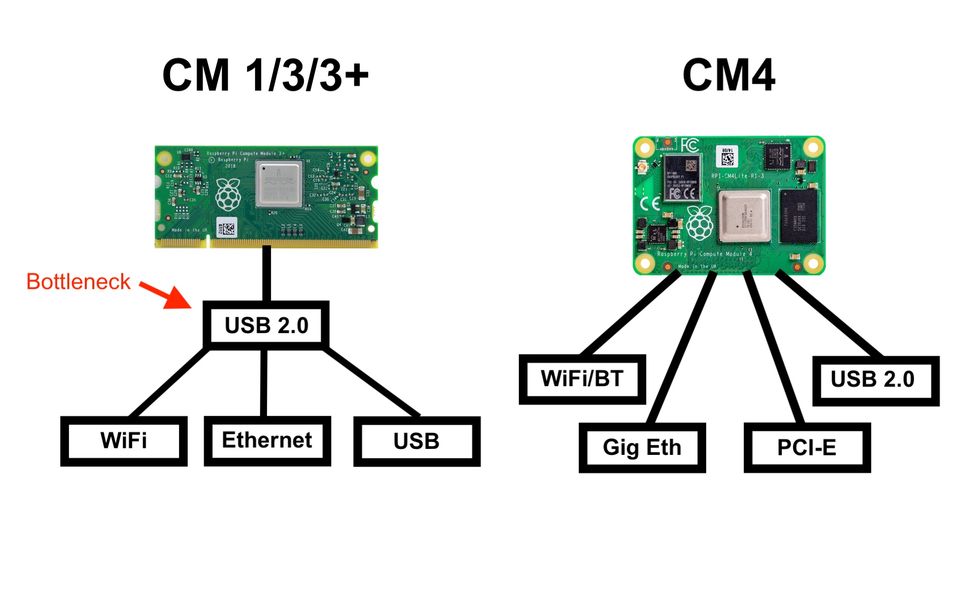
It turns out that on CM3 ALL our interfaces – Ethernet, WiFi (USB dongle), USB – had a bottleneck in the form of one single USB 2.0 output on Compute Module 3.
On CM4 we have:
- Independent WiFi 2.5/5GHz b/g/n/ac
- Independent 1Gbit Ethernet!
- Independent USB 2.0 (same as previous models)
- PCI-E
As a result, this affected the development as follows:
- WiFi – no need to integrate it on board or use a USB dongle. Ready out of the box!
- Gigabit Ethernet – just install a connector! Previously, to support Ethernet, we installed a LAN9513chip
- USB 2.0 – to give users additional USB connectors, we installed a Microchip USB2513 hub.
- PCI-E – in our case, there's no need for such furious speeds. We considered the option of installing a PCI-E -> USB 3.0 chip, but these solutions turned out to be either expensive or inaccessible. For example, the RPi4 uses a VLI VL805 chip.
WiFi and Bluetooth
What can I say? Both wireless interfaces are present and work great. You get them without any effort on your part. Of course, if you choose the CM4 with the respective wireless option. Both wireless modules, just like the ones on the Pi4, come with great driver support!
We'd like to emphasize the presence of a connector for an external antenna. This unties your hands to create long-range solutions. You can use 5 or 7 dBi dipoles popular with drone developers, or patch antennas, or even directional dishes (on the ground, of course). Please note that you need to select the antenna to use before booting the system. For this, the parameter is provided in the config.txt file.
A cite from the CM4 datasheet:
The config.txt options are dtparam=ant1 for internal antenna or dtparam=ant2 for external antenna
Changing the antenna 'on the fly' won't work.
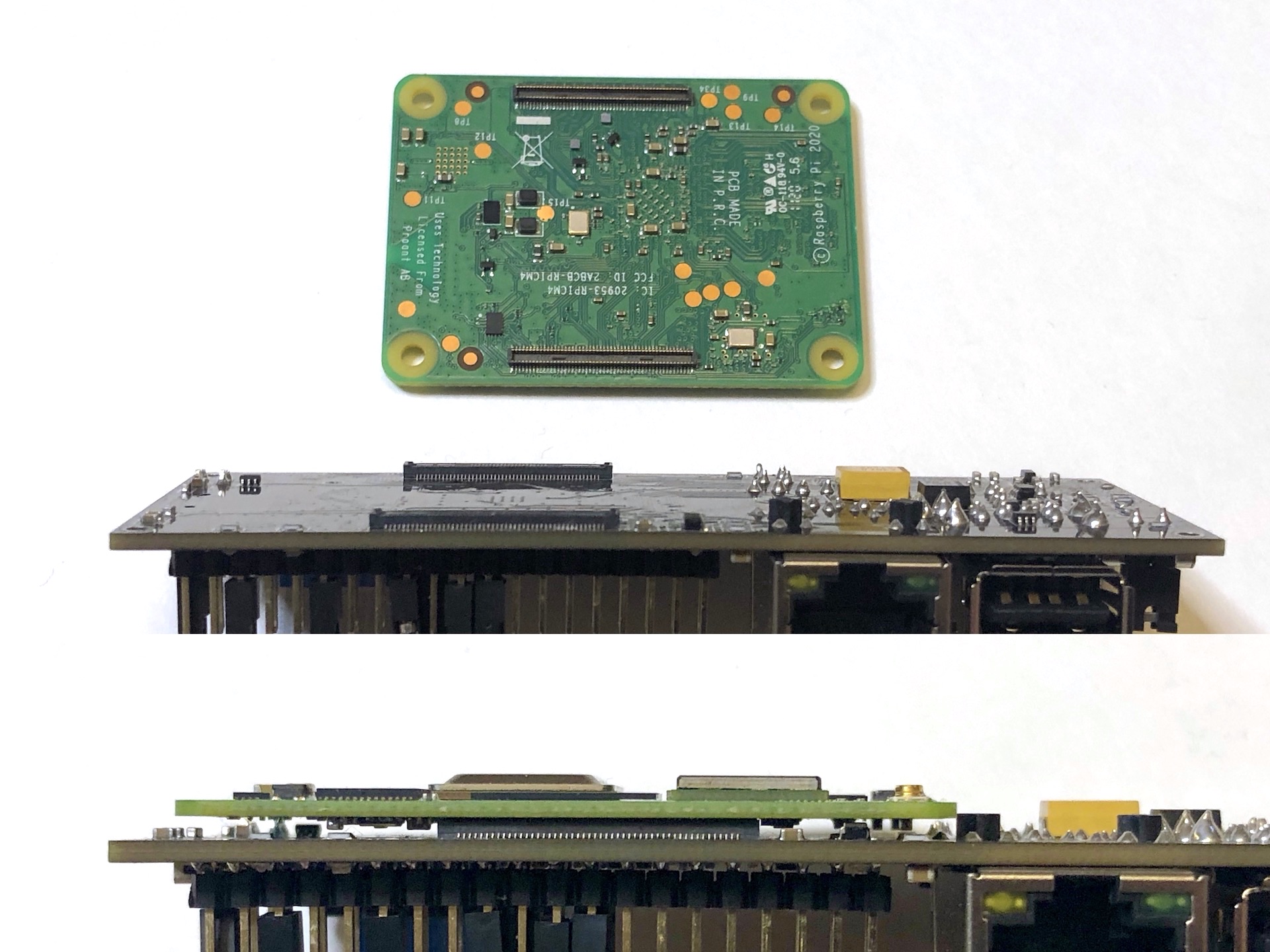
When we wrote 'without any effort', we cheated a little. In fact, if you plan to use the built-in PCB antenna of the CM4 module in your device, you need to consider its correct placement. RPF recommends placing the module so the antenna is as close to the edge of the board as possible. Also, you must provide an unmetallized 'window' on your board just below the antenna. Here's what this 'window' looks like in our setup:
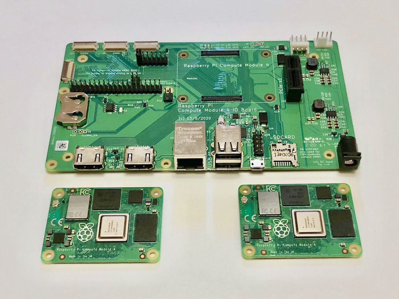
Pay attention to the evolution of CM4IO board. In the early version we had, the CM4 antenna was not on the edge of the board, plus, there were tracks right below it. In the final revision, the module was rotated by 90 degrees. We assume that one of the reasons for this change was precisely the issue of efficiency of the PCB antenna.
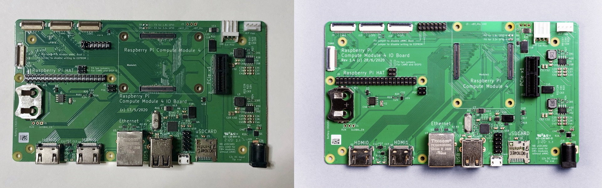
CM4IO board: early edition (left), release edition (right)
About wireless power and the joy of security fans
As we mentioned above, you can trace the history of changes of the CM4 on the restricted developer forum. In early revisions, the wireless interfaces were supposed to be powered separately. But then the approach was revised, WiFi and BlueTooth were switched to using the power source on the CM4 itself, and the two power pins gained new interesting functions. Introducing:
Pin 89: WL_nDisable
Pin 91: BT_nDisable
Each pin can perform two functions:
1. Power control
If you set the pin to level 0, the system physically turns off the power of the wireless interface. This can be done independently for both WiFi and Bluetooth. This is a very useful option both in terms of energy consumption control and in terms of special access to the final device. For example, in a final product, WiFi may be turned off, but an engineer can activate it to diagnose the device or change settings.
2. Indication of the current power status
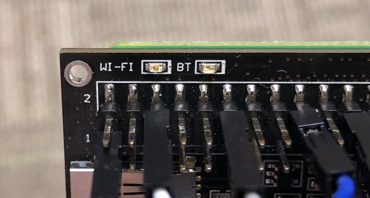
The same GPIO outputs can control through a buffer an LED that shows the interface's current power status.
We've added two LEDs to indicate the power status of the WiFi and Bluetooth wireless interfaces:
The current version of the datasheet has no details about programmatic access to managing these pins. On the restricted developer forum, Dominic replied that «Current the software turns on the power to the wireless and BT interfaces at boot time and doesn't turn it off». We can assume that these parameters may be quite 'delicate' in terms of security of final solutions, therefore they are not published at the moment. We'll have to wait for the details!
Our second failure
The description of the pins makes it quite clear that when the level is 0 (or below 0.7V), the interface power is turned off, when it's 1, it's turned on. But when discussing this within our team, a misunderstanding crept in here: if the pin is called WL_nDisable, then at level 1 the interface should be disabled. As a result, our early prototype showed the exact opposite state of the interface. For example, WiFi is working but the corresponding LED is off. The problem was solved without changing the PCB, but by simply replacing the LED buffer SN74LVC1G125DBVR with an one inverse, namely SN74AHC1G04DBVR.
Gigabit Ethernet
No special comments here. Everything works out of the box. Yes, the recommended reference Ethernet connector is not very common, but at the end of the day you can find either that one or a similar alternative.
USB HUB
Keeping with our tradition, we must provide the user with several USB ports. A couple of regular USB-A ports for connecting various USB dongles (mouse, keyboard, USB microphone, and so on). And for those who are saving space, the third port is connected with 4 pins. While a device connected to a USB-A port inevitably sticks out, the third port on pins allows you to place one USB device in the most convenient way for you using a flexible cable. For example, completely hide it inside the body of the device.
To solve this problem, we used a USB2513 hub. The CM4IO board from the Raspberry Pi Foundation uses the USB2514 version, which implements 4 USB ports.
Separately, we'd like to note that in order to 'pick up' this hub, you need to load the special overlay. This is done by writing a line in the configuration file:
dtoverlay=dwc2,dr_mode=host
Our third failure
If you look at the USB2513 datasheet, you will notice that this hub supports configuration via the I2C bus. Therefore, 'just in case', we hooked up an I2C when developing our PCB. It turned out that we don't need I2C for typical applications. And by the way, these microcircuit pins are not used on the CM4IO debug board either. Simply put, our hub was not working.
Whenever we do something 'just in case', we provide the ability to disable this feature without reworking the PCB. So it was this time too: two zero resistors were added to the I2C lines going to the chip. Unsoldering them solved the problem. We simply won't include them In the planned production device. But if you suddenly have an urge to tinker with the I2C option of the USB2513 chip, you should know that this option is available.
USB client (eMMC, RPiboot)
When developing the first version, we didn't take into account the habits of users working with a regular Raspberry. This was our fault. Most people tried to power the StereoPi through the micro USB connector, which was intended for other tasks (USB client mode and eMMC firmware flashing). As a result, the USB/LAN hub on the board disconnected automatically, and things didn't go according to plan for the users.
This time we've fixed this bug. Now, the USB client mode is not activated automatically, but when a separate jumper is put in place. The same goes for the eMMC firmware flashing mode.
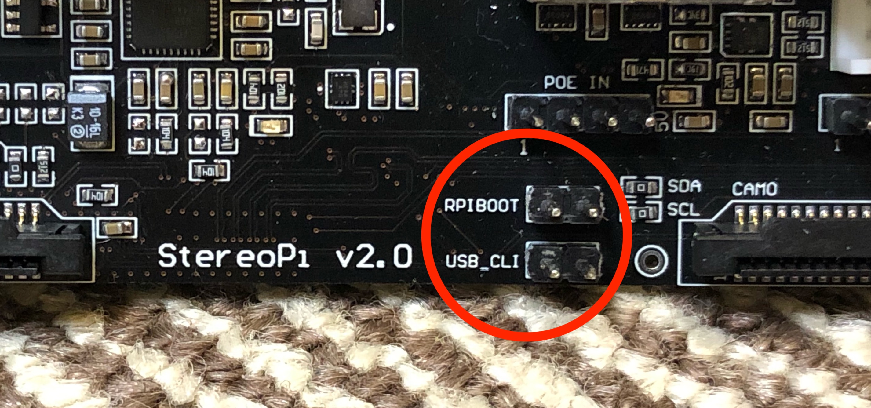
One interesting observation is that the last revision of CM4IO implemented an approach that we used on the StereoPi v1. While the engineering version of CM4IO required the installation of a jumper to access the eMMC, the latest version automatically turns this mode on upon detecting a micro USB connection (using the FSUSB42MUX chip). This is described in section 2.5 of the CM4IO board datasheet. This is exactly the case when a solution is absolutely 'in place' and doesn't create confusion for the user.
Power connector
As we mentioned in the previous section, our goal was not to break the established habits of Raspberry Pi users. Therefore, in StereoPi v2, the USB-C connector is used by default to power the board. And the additional JST connector is reserved for advanced users who want to save space by eliminating wires sticking out and get a reliable contact that can withstand stress and vibration (for example, on board a drone or robot).
But what about the simultaneous connection of two power supplies? After all, voltages could meet, and that's not good. While in the previous version we used a Schottky diode, in the new revision we installed a separate power switching chip, namely the TPS2121. Now, if you simultaneously apply power to both connectors, nothing dangerous will happen. Moreover, when one power source is disconnected, the system will automatically switch to the second one without interruption.
Fourth failure that made us worry
It seemed like a great idea to change power supplies on the fly without interrupting the device. A specialized microcircuit with everything done according to the reference design. But there was a problem while testing the device. If the device was powered from the JST connector and we'd plug in a USB-C cable, our StereoPi would reboot. The nuance is that connecting a power cable (especially a long one) causes side effects. Here's a quote from the TPS2121 datasheet (section 10.7):
Some applications require power muxing between hotplugged inputs, such as USB applications or systems with secondary supplies coming from a long cable. During a hot plug event, the inherent inductance in the cable and input traces can cause a voltage spike on the input pin (V = LCABLE * dI / dT). This can cause a voltage spike on the input of the TPS212x that could potentially exceed the absolute maximum rating.
In our case, we 'caught' the power protection actuation effect when using a no-name USB-C cable 2 meters long. When using a 2-meter charging cable from a MacBook Pro, everything works stably, as with a no-name cable 1.5 meters long. The conclusion is simple – use either high-quality or not very long cables. In the end, everything works well, and you can actually hot-swap power supplies.
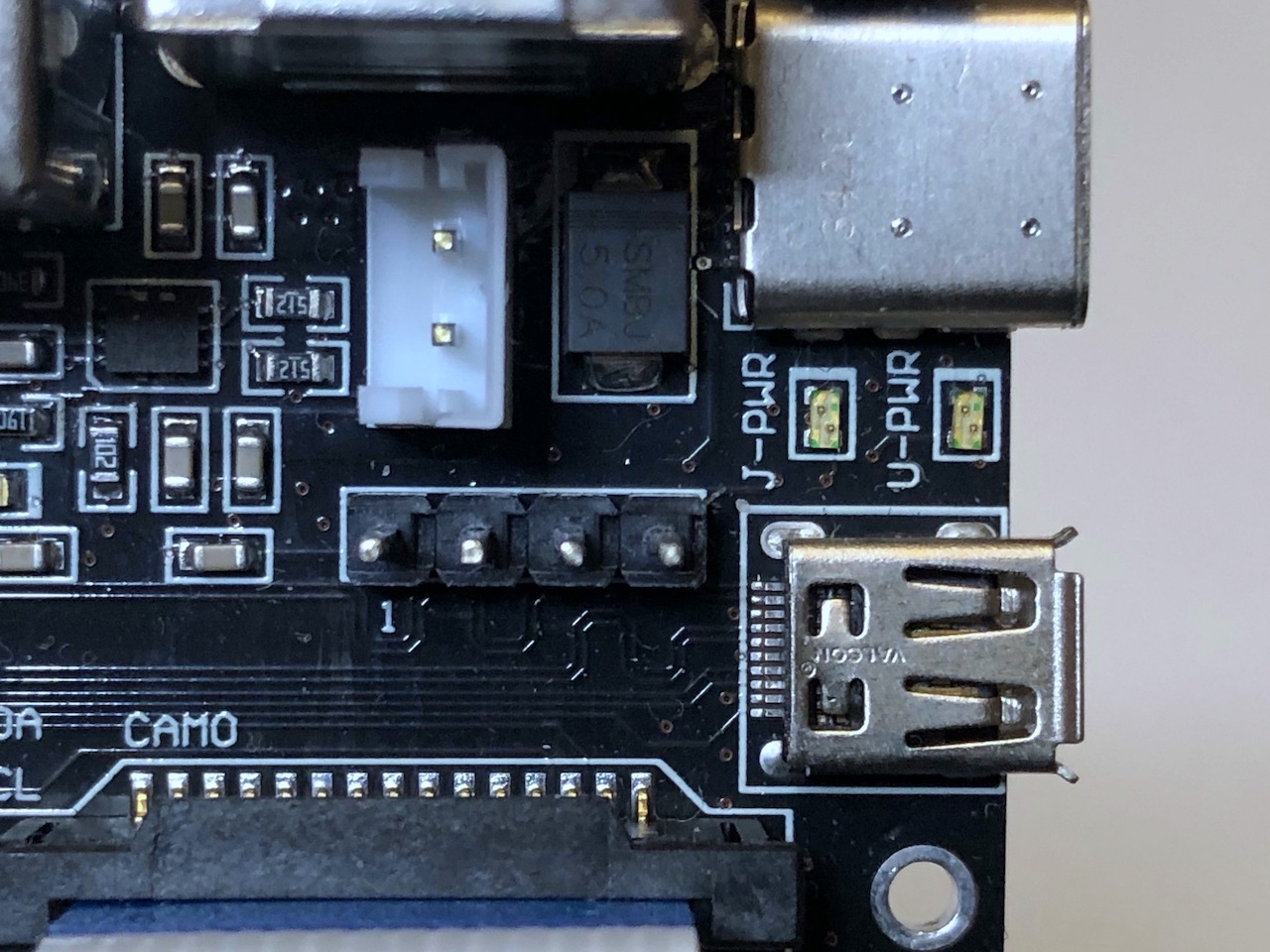
We added two bi-color LEDs for better user convenience. They indicate the presence of power at each input, and also indicate the active input from which power is currently being drawn.
Power switch
In v1 we added a useful option – a power switch. On a classic Raspberry Pi, you need to unplug the power cable to completely switch off, and plug it back in to power on again. In our case, this is fraught with loosening the connectors, and simply inconvenient for the user. We still consider the power switch to be one of the most convenient options of our device ☺
By the time we started developing v2, we collected feedback from our users. In addition, we took into account the specifics of the CM4, and before developing v2 we had the following list of facts to comprehend:
- The switch is convenient and necessary. It should definitely be present in the second version.
- In v1, the switch is rigidly fixed to the board. Its location is not always convenient for the user (sometimes it needs to be located in another part of the case).
- The length of the switch lever is such that after installation in a case it protrudes only a fraction of a millimeter. This is inconvenient.
- All the current in the power supply line passes through the switch. The peak loads on the CM4 may be higher and our little switch may start to warm up (since it's not designed for high currents).
We decided to proceed as follows:
- Instead of placing the switch on the board, we brought out two pins. Connecting the pins supplies power. If you install a jumper on them, then you can work with the StereoPi as with a regular Raspberry Pi, namely: supplying power with a USB-C cable turns the device on.
- Instead of a jumper, you can connect a suitable power switch on two jumping wires, and place it anywhere on the body of your device.
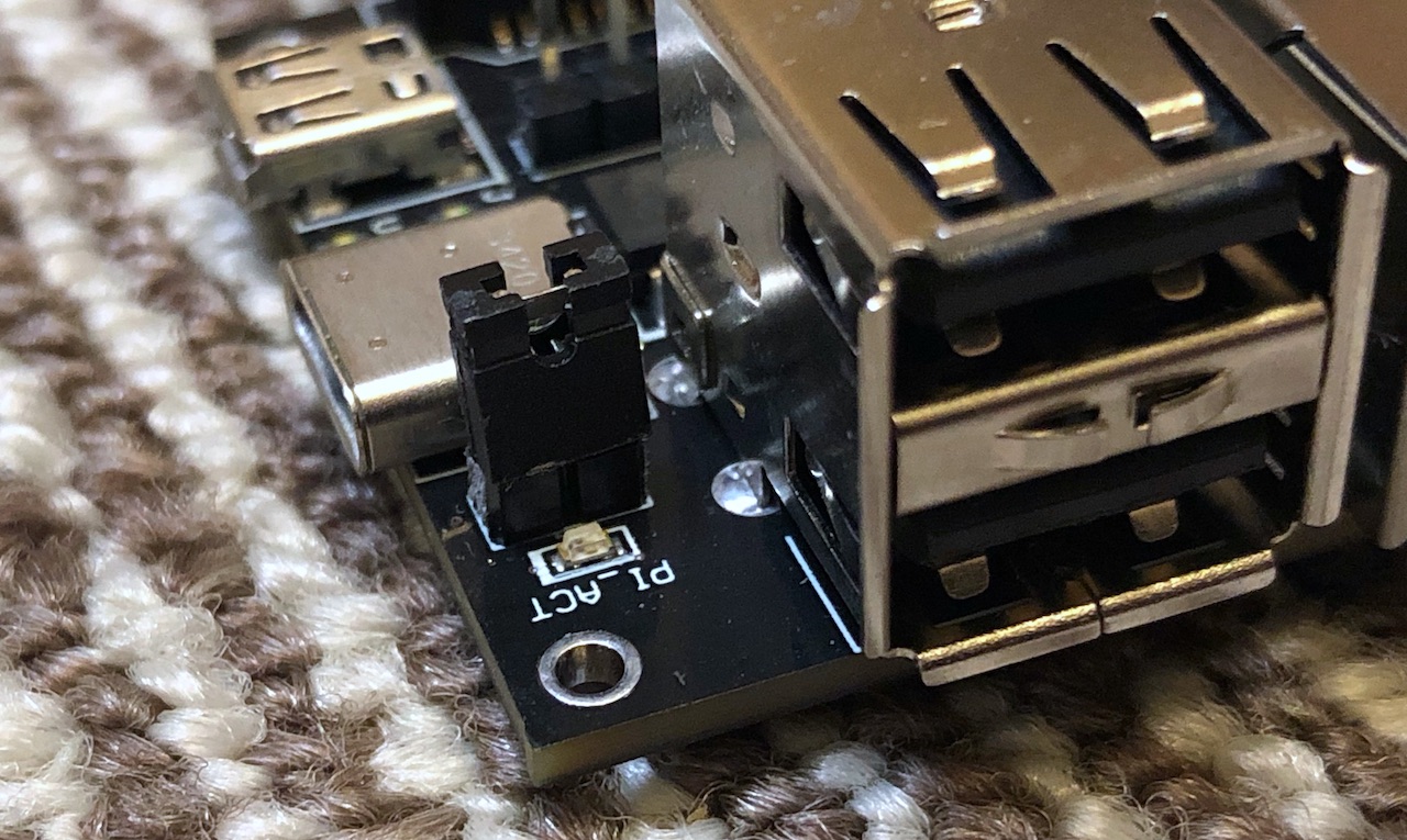
And the most important thing. These power pins do not pass all the current drawn by the device through them. They control the operation of the load control chip (TPS22965DSGR). This means that you can use even very tiny switches designed for low current!
PoE
We received several requests to support Power over Ethernet, specifically PoE. To accommodate this, 4 additional pins are available on the v2 board for connecting the additional PoE HAT. After processing the raw PoE power and converting it to the 5V we need, it will be sent through the JST connector to our power mixer. We'll talk about the details of the implementation of this module a little later.
Micro HDMI
Our failed trick of placing large USB-A and Ethernet connectors above the CM4 forced us to look for new approaches to saving space. One solution was to use a micro HDMI instead of a full size HDMI connector. Our task was to find a connector that would combine reliable fastening to the board (i.e., having a group of pins that go through the board, and not just for surface mounting), as well as the convenience of connecting an HDMI cable. We really liked the connector used on the Raspberry Pi 4, especially the 'bell' opening that makes it easier to get the plug into the connector. So we started looking for it.
The search proved to be a daunting task. Any queries on Google for the words 'hdmi, raspberry, part number' produced a huge number of articles about the specifics of configuring the HDMI outputs of the Raspberry Pi, but not what we needed. We were about to ask RPF a direct question, but decided to do an image search using the phrase “micro hdmi connector”. Scrolling down a few pages, we found our hero:
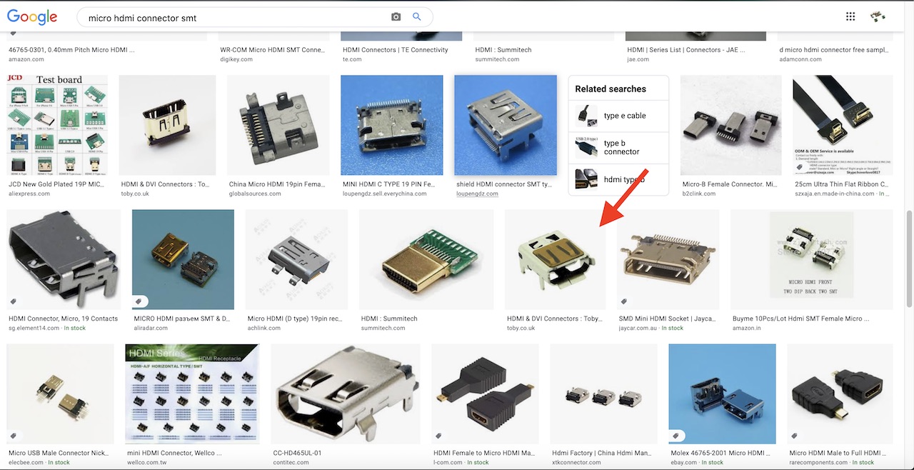
It turned out to be the HD-RA-DSF12-TR connector by Toby Electronics.
We contacted Toby and asked for a 3D model of the connector to install it on the board.
By the way, we simply unsoldered the connectors from several of our Raspberry Pi's for producing the very first prototypes.
It's an honor to be a donor
Fifth failure – micro HDMI

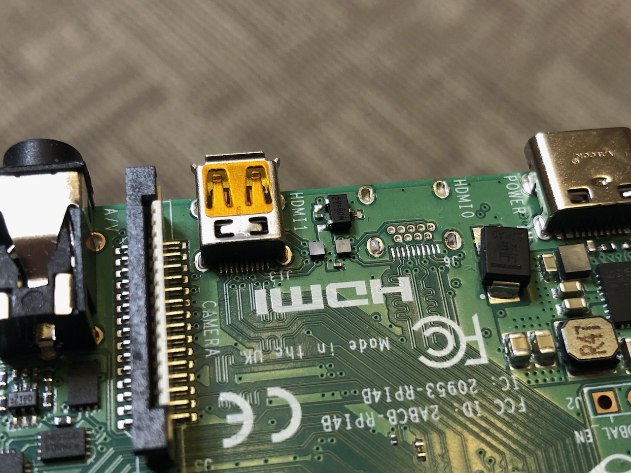
Can you guess what's shown in this photo?
Hint: This dirty workaround was made for a quick test of an idea for why we have these colors:
Now for the details. If you've already used an HDMI connector while designing your devices, you know that it has 19 pins. And the micro HDMI connector (it's more correct to call it HDMI type D) also has 19 pins. Here, look at the picture:
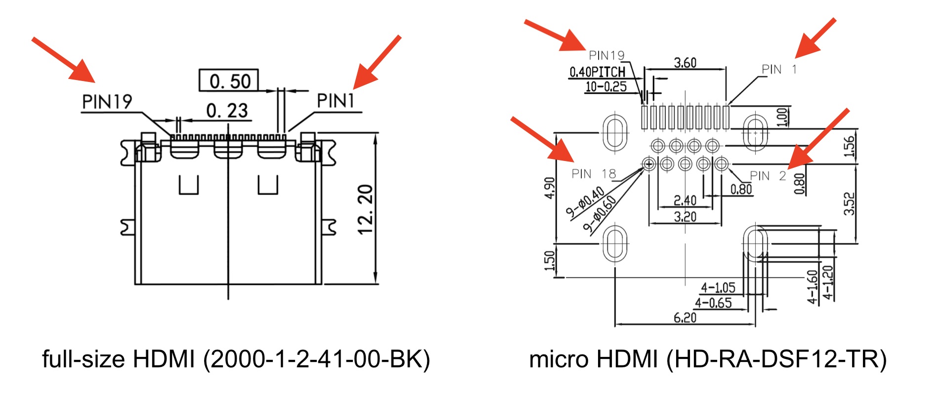
Yes, we made a mistake and just installed an HDMI type D connector in the circuit, keeping the connections with the pins according to their numbers.
The catch is that the electrical (signal) pin assignments for HDMI-A and HDMI-D are different!
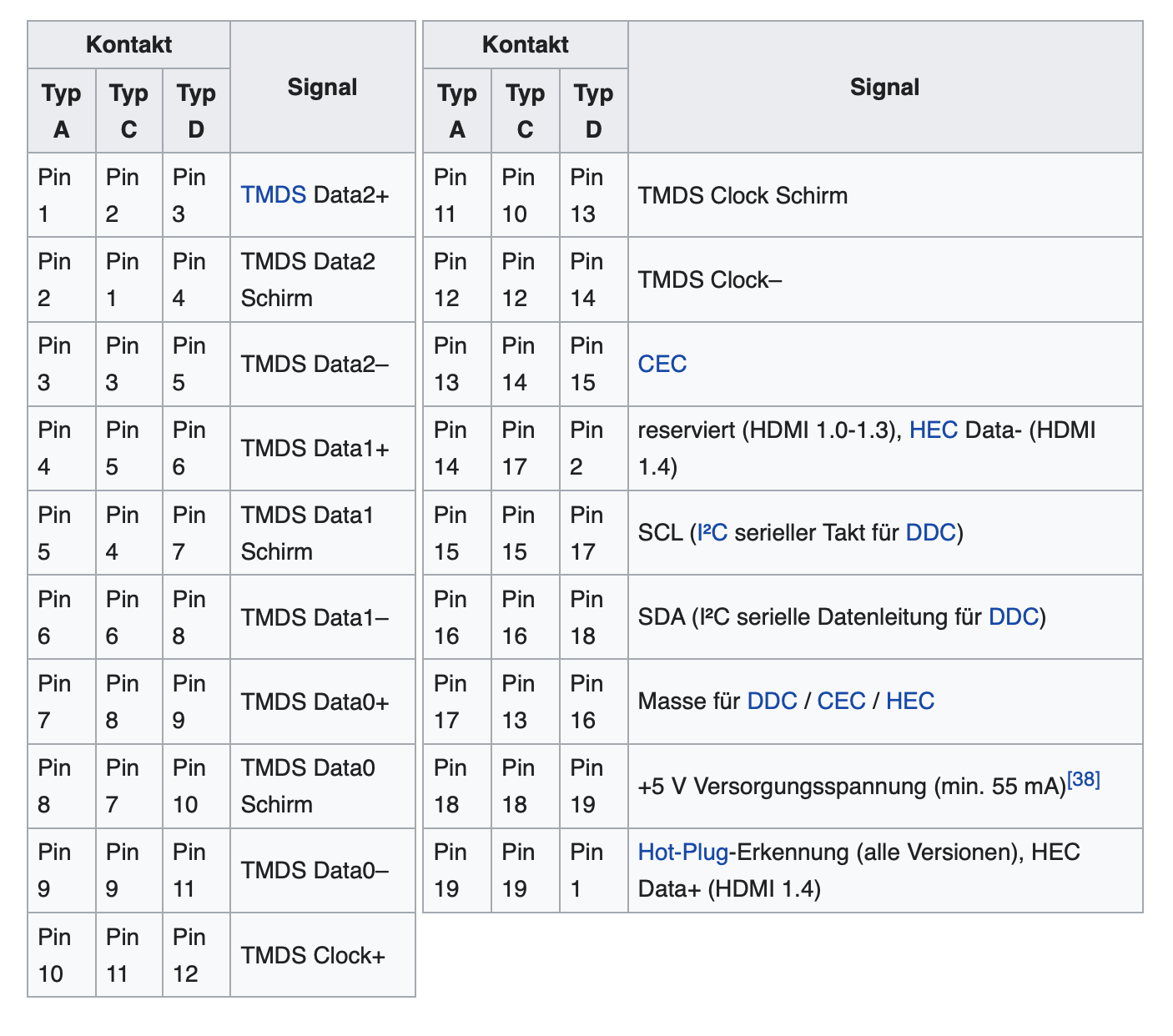
Source: https://de.wikipedia.org/wiki/High_Definition_Multimedia_Interface#Stecker
I shared this error with an electronics development team I know. The guys laughed and said that they made exactly the same mistake while developing their device. And they offered me a ‘converted’ HDMI to micro HDMI cable, which they once made for the same purpose as we do. But we already had our own.
So pay attention!
HDMI and built-in ESD protection inside
We planned to add ESD protection for the HDMI line on the board. But a new update of the datasheet on the restricted CM4 forum mentioned that it was already present on board the Compute Module 4. What does this mean? Even fewer components on our board compared to v1. Another nice CM4 bonus!
Cameras
Just like in CM3, we have here two CSI-2 buses for working with cameras. For CM3, developers could use different pins to connect cameras (adjusting the device tree for their solution). In CM4, the camera connection lines are unified (these are the even pins from 128 to 142 for one camera, and the odd pins from 115 to 129 for the second camera). In theory, this means that all solutions with stereo mode support on CM4 can use the same dt-blob.bin
Now that’s convenient!
One of the feature requests from StereoPi v1 users was for more options for connecting cameras. In particular, the possibility of non-standard connections of I2C lines, or access to unused lines in the camera bus. Such needs often arise when connecting third party camera modules. Therefore, we have included a couple of special capabilities.
1. Camera LED
The first version of the Raspberry Pi Camera v1 had an LED on the board. It’s not used in the next generations of v2 and HQ cameras. But the line previously used to control it remained in the camera bus, unused. But physically getting to it is very difficult. Some camera developers (for example, Soho Enterprise) use this line for hardware synchronization of their two sensors. Therefore, in v2 we did this: this line is brought out of the bus to a contact point on the board. This means that you can physically connect any signal to it, be it from a GPIO header, or even from an external device. You get full control.
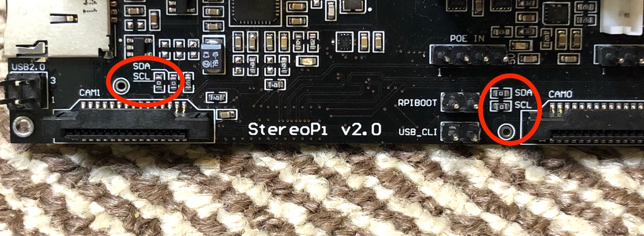
2. I2C
When working with industrial sensors (not supported out of the box by Raspberry OS), developers often need direct access to the I2C lines of both cameras. StereoPi v1 users most often used a camera breakout board for these purposes, which allows physical access to the desired signals. In v2, we added a special feature for advanced users. The I2C lines of both cameras have 0 Ohm resistors located on the board next to the camera connectors. You can remove these resistors and make the line connections you need to achieve your goal.
A few words on the board’s cost
Since the CM4 is a highly integrated device, we had the opportunity to simplify the StereoPi v2 circuitry in comparison to the previous version. Therefore, during development, we kept in mind a lower total cost for the device. For example, we managed to make the board in 4 layers (versus 6 layers in v1). We have strived to use relatively large components (0603) to reduce the class requirements for the assembly line. The CM4 onboard power module allowed us to ditch our own power block, which also reduced the cost. As a result, the price will be at least 30% lower than that of the previous generation. In doing so, we were able to add several new features!
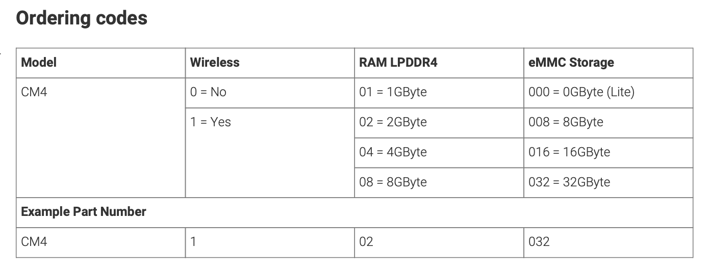
Which CM4 we chose and why
As you know, the CM4 is available in 32 variants. Its variable options are the wireless module, RAM size and eMMC size. So which one did we choose for our sets?
Wireless
This one is definitely needed! With a Compute Module price increase of just $5, you get WiFi and Bluetooth (and the ability to connect an external antenna).
RAM
For our typical applications (streaming/recording video and computer vision), we rarely need more than 1 GB. But there are cases (for example, compiling OpenCV from source) when 1 GB is already tight. Therefore, we settled on the option with 2Gb RAM.
eMMC
The most comfortable way to work for the average user is using a micro SD card. Therefore, we will equip our kits with the Lite version.
According to the numbering, the Compute Module 4 we have chosen has the following part number: CM4102000
By the way
Our crowdfunding campaign will be starting soon. You can subscribe to notifications from Crowd Supply so you don’t miss the start!
Conclusion
Our team would like to thank the Raspberry Pi Foundation for providing early access to technical information and the support they provided during development. We sometimes asked ‘newbie questions’, and received polite and comprehensive answers to all of them. Thank you!
Special thanks go to my friend Jason and his company Villmer LLC, who tipped me about the CM4 program. Like StereoPi, Villmer LLC is also developing new CM4 hardware devices for its subsidiary company POP.
I’d also like to thank my friend Paulo Fino for his help with text translation and tech review.
Useful links:
The Raspberry Pi Compute Module 4 Review by Jeff Geerling
CM4
http://datasheets.raspberrypi.org/cm4/cm4-datasheet.pdf
http://datasheets.raspberrypi.org/cm4/CM4-step.zip
http://datasheets.raspberrypi.org/cm4/CM4Lite-step.zip
CM4IO
http://datasheets.raspberrypi.org/cm4io/cm4io-datasheet.pdf
http://datasheets.raspberrypi.org/cm4io/CM4IO-KiCAD.zip
BCM2711
http://datasheets.raspberrypi.org/bcm2711/bcm2711-peripherals.pdf