A robot on StereoPi, part 1: fisheye cameras
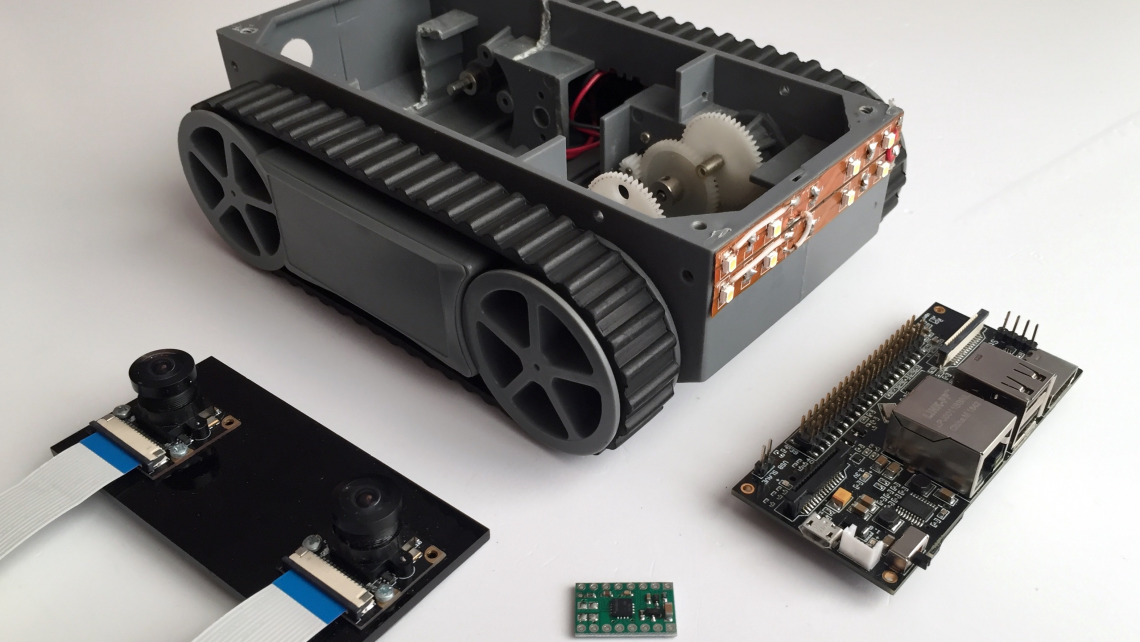
The goal of this series of articles is to create a compact indoor robot that can navigate using stereo vision. As a platform for it, we’ll use a small Dagu RP5 platform on tracks that we have. Here’s how it looks like next to the StereoPi.
Unlike planes and copters, it won’t be able to fly away. At the same time, it won’t cause any damage to furniture or make a mess during tests, like its heavier counterparts can.
Since we want the StereoPi to perform all robot control functions at once, we need to take into account all the ‘delicate spots’ of Raspberry Pi performance in this case. We’ll dedicate special article sections, and even whole articles, in this series to these ‘tweaks’ and ‘hacks’. For example, we will use the stereo cameras in scanning lidar mode, and we’ll also cleverly bypass some hardware limitations to increase our solution’s FPS. But each thing in its own time!
Wide-angle cameras
I remember very well one of the very first experiments our team did with remote controlling a model car equipped with a camera. We did the tests in our office, the car was in one room, and I was in another one nextdoor. I connected and saw the picture from the camera. I hit ‘gas’, but the car jerked weirdly and slowly ‘drifted’ to the side. Not understanding what was going on, I decided to back up a little. And then everything fell into place. On the left side of the camera image, I saw the leg of an office chair! Our crawler was pushing against it with the left side of its body. But I wasn’t able to see this through the camera. Why? Because the camera had a regular angle of view (about 50 degrees). Almost 10 years have passed since then, we have done a lot of projects for radio modelers, and have learned well: the bigger the camera angle, the better. We prefer to use optics with an angle of 160 to 220 degrees.
Let’s look at a simple example — we’ll shoot the same scene from two Raspberry cameras positioned side by side. One of them is a regular V2 camera with an angle of 62.2 degrees (according to its documentation), and the other one is a 160 degree Waveshare G wide-angle camera.
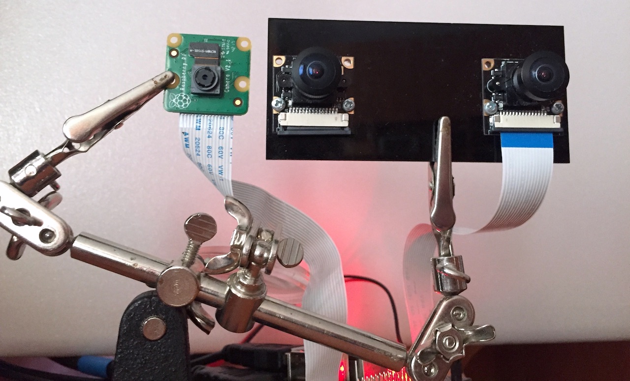
We quickly built this simple contraption for the photoshoot:
Let’s look at the difference between the images from the two cameras:
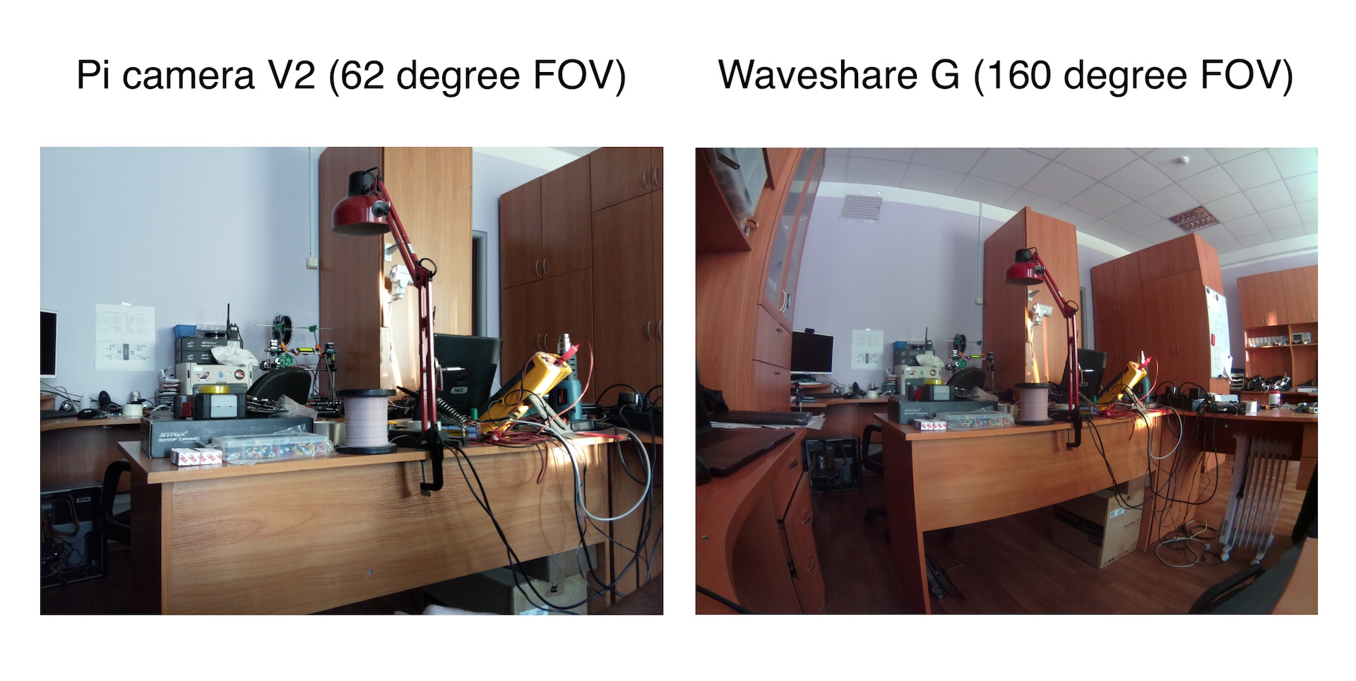
Obviously, the wide-angle camera sees SIGNIFICANTLY more than the regular one. But you can use cameras with 200-degree angle optics, then the field of view will be even wider! For example, the Waveshare M’s that we used in our experiments with 360 degree photos.
Hence, the first conclusion — our robot needs wide-angle optics. Therefore, we’ll use the Waveshare G cameras (which, by the way, came included in Deluxe StereoPi kits).
Software
For this series of articles we took the codebase of our stereopi-tutorial examples, but made significant changes to them. If you haven’t seen the previous article yet, I recommend you take a look, since the codebase and approaches are taken from there.
The goal is to get a spatial map of the environment for the robot to orient itself. For this you need to build a depth map. But in order to do this it’s important to calibrate the cameras (since it’s impossible to install them absolutely parallel). For calibration, you need to take a series of shots and use them to do this very calibration. To perform each of these steps, we developed a separate script, which I’ll describe further.
Here is our Github repository stereopi-fisheye-robot.
1. Test script — 1_test.py
This script is used to test system health and performance. It hasn’t changed much since the previous tutorial. To exit the script, press the Q button on the keyboard. On exit, the script saves the last frame as an image. It may come in handy later for you to fine tune your depth map. Therefore, before pressing Q, turn the stereo camera away from your face (where it’s usually pointed at during first tests), and point it to a stage with objects at different distances.
2. Script for shooting a series of frames for calibration — 2_chess_cycle.py
This script is also similar to the one from the first series. Shooting the calibration series has its own nuances, but you still won’t read this until you have problems with calibration, so we’ll describe them later. ☺
The script will output and save 30 images with a calibration chessboard overlay, which the system will use for calibration.
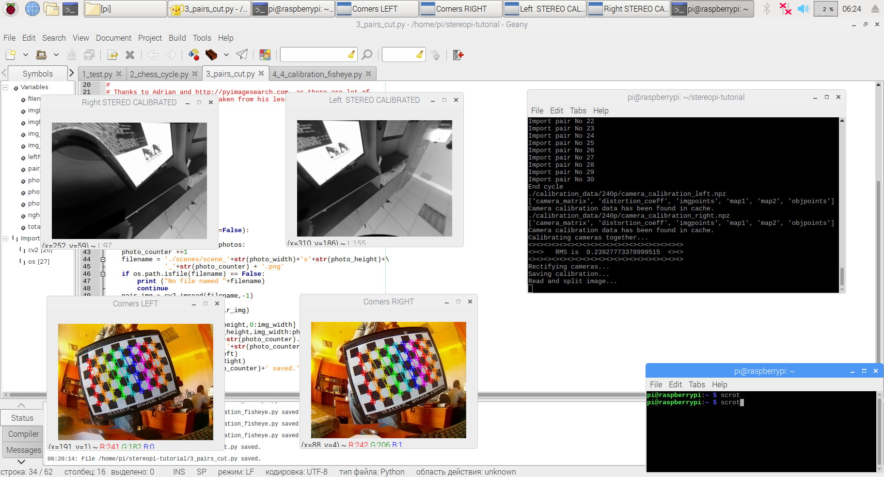
3. Cutting images into pairs — 3_pairs_cut.py
This script cuts frames from the last stage into left and right photos. This simplifies work and further debugging. The script’s logic has not changed at all from the previous manual either.
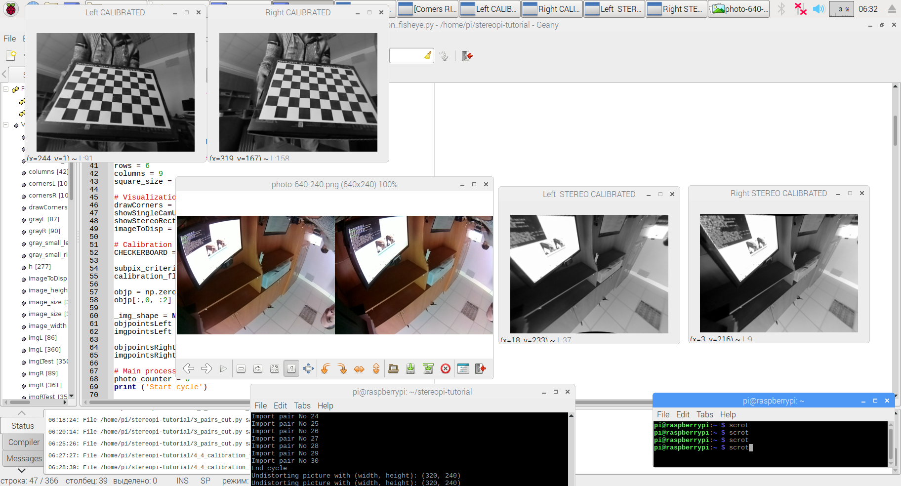
4. Let’s calibrate! — 4_calibration_fisheye.py
‘What’s the problem? Just start the calibration from the previous example — and Bob’s your uncle!’, you might think. Not so fast. We’re done with the short script descriptions, and we move on to the TL;DR part.
Let’s try to dive a little deeper into cold water. The calibration script from our previous stereopi-tutorial is designed to work with ordinary cameras. If you run images from wide-angle cams through it, at best you’ll get images looking normal in the center and distorted at the edges, and at worst you’ll get incomprehensible avant-garde-style drawings.
The reason is simple: there are two separate camera models in the OpenCV libraries — the regular (‘pinhole’) and the wide-angle (‘fisheye’). The latter is distinguished by the presence of two additional parameters in its mathematical model, namely the matrices K and D. Are you scared yet? Don’t worry, we’ve already added these parameters to the current version of the script. They will be calculated automatically.
Let’s dive a little deeper for a moment, for the sake of the most inquisitive people. In the previous version of our scripts, we actively used external stereo-vision calibration libraries, which did a lot of work for us ‘under the hood’. In this edition of the scripts, we pulled all the magic right into our script code. Yes, they have become a bit heavier and somewhat harder to analyze, but now all the stuff is in front of you, and the scripts have no dependencies on third-party libraries. If you read up to this point in this paragraph, then you are one of those who will feel compelled to play with all the available parameters. To finish this paragraph, I’ll share with you one of the most successful analysis of the practical use of the wide-angle camera model in Python:
Calibrate fisheye lens using OpenCV — part 1
Calibrate fisheye lens using OpenCV — part 2
Now let’s return to our muttons. If you look at the script code, you’ll find the following logic (simplified):
– First, we calibrate each camera separately to remove barrel distortion. At this stage, the picture from the left and right camera is ‘straightened’.
– The second step is to calibrate and rectify the stereo pair, passing to it the discovered parameters of each camera.
If you turn on all the variables to True in the # Visualization options section, the script will show you all the steps, starting with the search for the chessboard, displaying the ‘corrected’ pictures from each camera separately, and ending with the rectified stereo pair.
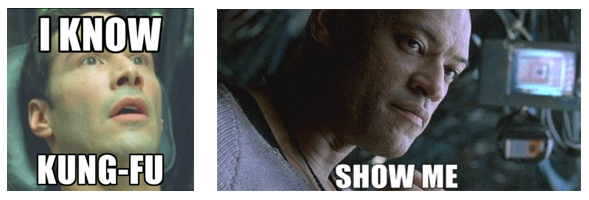
Well, now you seem to know kung fu already, don’t you? Where’s that depth map?
Once more, not so fast. We are solving an applied problem here, so I simply have to tell you about bypassing two more traps.
Trap 1 — capturing stereo video at low resolutions
As you may remember, for ease of calculation, we work with a resolution of 320x240 (we’ll cover the issue of increasing it in following articles). But if you capture the stereo pair straight away in the 640x240 resolution needed, the picture will have glitches (offsets and green bars). This is a bug in the implementation of PiCamera, and it can be bypassed by capturing a picture with twice the resolution (1280x480), and then reducing it by half using the GPU (with no load on the main processor). This solution was already implemented in past scripts, but I’m highlighting it for those who are just getting acquainted with the topic.
Trap 2. Suspense…
The second trap is more interesting, and users of our stereopi-tutorial scripts often fall into it, even with regular narrow-angle cameras. The bottom line is that you can get bad or very bad calibration results with seemingly good input images. When using the old logic, you can get results like these, for example:
How do you like the beautiful ‘curved’ distortions in the upper left picture? This is just a small manifestation of the problem.
The reason is quite simple. Since our working resolution when building the depth map is 320x240, we used it in all scripts, including the calibration ones. But at such small resolutions, the algorithm for finding the chessboard corners often makes mistakes — it either doesn’t find the corners at all, or finds them in the wrong places and mismatches their sequence. The problem is exacerbated when using wide-angle cameras. Therefore, we decided to use a lifehack in these scripts: use higher resolution images for calibration, and then use the calibration results on smaller images!
Despite the simplicity of the idea, its implementation required some serious digging into the code. Yes, the wide-angle cameras’ K and D matrices don’t depend on resolution. But in almost all the calibration and rectification functions you have to pass the image resolution, and simply replacing it with the one you need completely breaks the results.
Finally, we chose not the prettiest, but an understandable and manageable way around it. In the process of calibration the scripts believe that they are working with a resolution of 320x240. But at the time of chessboard corner search we cheat, namely:
– to search for the corners’ coordinates, we feed images with twice the resolution.
– after finding the corners’ coordinates, we reduce all X and Y coordinates by half.
– the coordinates reduced by 2 times are passed on to processing, and the substitution goes unnoticed.
In practice, this made it possible not only to get correct angle coordinates without any errors, but also to correctly find angles on those images where, with a smaller resolution, angles were not being found at all.
After applying this magic, the results of our calibration started to look like this:
What does this mean? It means that if you need extremely accurate calibration, you can take pictures with a resolution of, for example, 4 Mpix, calibrate on them, and then use this data at lower resolutions. Of course, these high resolutions must be multiples of your working resolution. Thus, for a 640x240 working resolution of a stereo pair, you can calibrate it using pictures at 1280x480 and 1920x720. If you have a V1 (ov5647) sensor with a native resolution of 2592x1944, then the maximum real resolution for calibration will be 2560x1920, which is 4.9 Mpix.
It’s not time to relax yet, we’re not done yet. Remember the description of the script number 2 and my comment about the nuances that no one reads about? Well, if you don’t read about them and don’t take them into account, then even following all the steps in our scripts very carefully will give you only mediocre results. All sorts of funny things like ‘glue the chessboard onto a flat surface’, ‘be generous with lighting’ and other nonsense which turns out to be (suddenly!) an unexpected salvation after three days of unsuccessful calibrations. I won’t repeat what has already been perfectly described by many people, but I’ll provide a link to one of the most concise and competent descriptions of these nuances on stackoverflow. Check out the first two answers to this question at Stackoverflow. Look through, add to bookmarks, and then read if nothing else helps ☺
5. Setting the depth map parameters: 5_dm_tune.py
Yes, we’re finally done with the long description of script number 4. You probably already started thinking that I decided to troll you. But no, there really were a lot of important points there.
The fifth script has undergone only minimal changes, mostly in how it rectifies the image in accordance with the new code for fisheye cameras. To make this section less boring, I’ll post here a short video from our first article, describing how it works:
6. Depth map with video: 6_dm_video.py
Honestly, we didn’t plan to post this script in the very first article of this series. But then we thought that in anticipation of the following articles, someone would like to play around with the results already available for wide-angle cameras. So we ended up simply adapting the script to the updated logic, and you can now use it.
If you decide to repeat all the above scripts on your StereoPi and get to the sixth one, the result will puzzle you a bit. The code can be easily adjusted so that the result is similar to that of our stereopi-tuturial. And those who decide not to adjust the code will get a hint about the direction in which we’ll move on from here in the continuation of our series of articles.
See you in our next publications!
Github repo: stereopi-fisheye-robot
Our wiki lives here: wiki.stereopi.com
And the forum is here: forum.stereopi.com
P.S.
Oh, and if you run the sixth script, look at the displayed depth map calculation time for each frame, and translate it into FPS. We leave the conclusions to you, dear reader!
Special thanks:
- Adrian and pyimagesearch.com
- RPi-tankbot project: https://github.com/Kheiden/RPi-tankbot
- Rakali project: https://github.com/sthysel/rakali