StereoPi used as USB device

The Raspberry Pi Compute Module powering the StereoPi has the ability to operate as an USB device thanks to an USB-OTG hardware within the processor. This means that we can connect it to the PC and make it appear as an USB stick, a serial interface, or – as exposed in this article – as an external network interface. It is very powerful but it comes with a few limitations due to the architecture of the Raspberry ecosystem followed by the StereoPi. Let’s see how it works.
Overview of the hardware
Appearing as a device requires a special hardware. Fortunately, in the case of the Raspberry Pi Compute module, the processor has one USB port which has the OTG functionality. It means that it can act either as a host (like a PC) or as a slave (like a USB device). Notice that the StereoPi can be entirely powered through the micro USB connector in the case it is used as a device.
The processor has only one USB port, which is problematic because the norm precises that it is not possible to connect multiple devices per port. Furthermore, the processor do not have any Ethernet controller internally. To circumvent these two facts, a special chip named LAN9513 is connected to the USB port of the processor and acts both as a USB extender providing 3 USB host ports (two of which have a USB connector on the StereoPi while the third is available on a pin connector) and as an external network interface with the associated Ethernet port on the board.
On the StereoPi, there is an additional component: an electronic switch named FSUSB42UMX, which allows to choose to connect the LAN9513 or the micro-USB connector to the USB port of the processor. The switch to the micro-USB connector is automatically done when the cable connected to it is under power.
Let’s draw a synopsis to visualize this architecture:
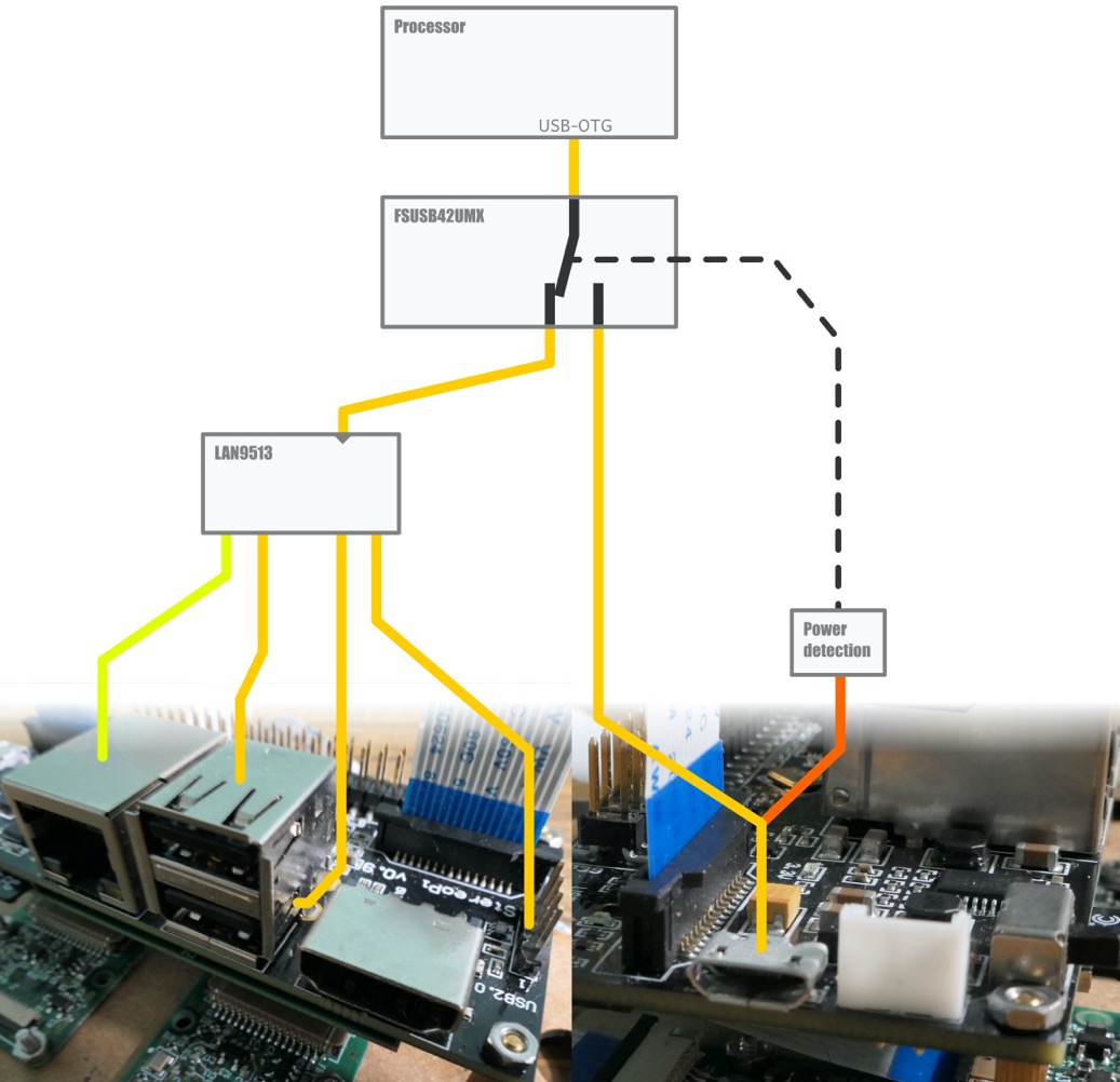
Legend: Synopsis of the hardware of the StereoPi focused on the USB subpart.
As we can see, the limitation is clearly that we will lost Ethernet and USB connectivity when using the USB device mode, because they will not be connected to the processor anymore. Fortunately, we can create a network through the USB cable to connect to the StereoPi as we will see afterwards.
If you tried to plug the board into your computer now, you would see that Ethernet and USB devices would cease to function. However, no device would appear on the PC because of the lack of software part in the StereoPi.
Overview of the software
To appear as a USB device, we have to enable the USB port in slave mode and then make the board behave as a device thanks to the kernel's USB gadget functionality. We will also have to enable a service to give an IP address to the PC automatically for convenience.
Unfortunately, because the usage of the device mode removes Ethernet and other USB capabilities of the board, and with them the ability to communicate easily with the board, we will have to prepare all the software stack in one run without progressive steps.
USB gadgets are kernel drivers that allow a Linux system (with appropriate hardware) to act as USB device. A specific API allows developers to write such drivers, but fortunately, there exist some generic drivers with common functionalities, already written in the Linux sources. These drivers allow the board to be discovered as serial link, human interface device, USB stick, etc. In our case, we will use an USB gadget which will transform the StereoPi to an Ethernet-over-USB device.
Notice that only one gadget driver can be loaded at the time. In the SLP distribution provided with the StereoPi, the gadgets are compiled as kernel modules, so that they are ready to be used without compiling anything.
When built as modules, the drivers are not included into the kernel binary image. They become auxiliary binary files (.ko extension is used for kernel objects) that can be dynamically loaded into the kernel at runtime. These files must be present in the target's filesystem to be used. In the case of our gadgets, they are located in /lib/modules/[kernel version]
Preparing the future network interface
/etc/network/interfaces.d/usb0
with the following content:
auto usb0
allow-hotplug usb0
iface usb0 inet static
    address 192.168.3.1
    netmask 255.255.255.0
    network 192.168.3.0
    broadcast 192.168.3.255
/etc/dnsmasq.d/usb0
with the following content:
interface=usb0
dhcp-range=192.168.3.10,192.168.3.250
This will allow the system to automatically attribute an IP in a valid range for our case to the computer which will send a DHCP request on the USB network interface.
Enabling device mode (and revert)
dtoverlay=dwc2,dr_mode=peripheral
modules-load=dwc2,g_ether
Benefit from your new feature
$ ping -c 5 192.168.3.1

PING 192.168.3.1 (192.168.3.1) 56(84) bytes of data.

64 bytes from 192.168.3.1: icmp_seq=1 ttl=64 time=0.157 ms

64 bytes from 192.168.3.1: icmp_seq=2 ttl=64 time=0.223 ms

64 bytes from 192.168.3.1: icmp_seq=3 ttl=64 time=0.291 ms

64 bytes from 192.168.3.1: icmp_seq=4 ttl=64 time=0.218 ms

64 bytes from 192.168.3.1: icmp_seq=5 ttl=64 time=0.244 ms

--- 192.168.3.1 ping statistics ---

5 packets transmitted, 5 received, 0% packet loss, time 4064ms

rtt min/avg/max/mdev = 0.157/0.226/0.291/0.043 ms
Troubleshooting
1. USB power
If you connect StereoPi to the USB 2.0 port on your desktop/notebook, power provided by this port might not be sufficient to feed up StereoPi (as USB 2.0 current is limited by 500 mA). Please use USB 3.0 port.
2. Dnsmasq
Dnsmasq is already installed on Raspbian S.L.P. image, but not installed by default on a stock Raspbian. To install it, use this command:
sudo apt-get install dnsmasq
3. Windows RNDIS driver problem
Under MacOS and Linux, the StereoPi will be detected and automatically configured. But with Windows 10 you can get a situation, when StereoPi is detected as a COM port. This is a known problem (for RPi and other single board computers), mentioned in a lot of places like Microsoft support forum. To say briefly, you can install this driver manually according to this guide (French), and it works.
Author: Stereomaton